The selection of the magnetic components to be used in a Switch Mode Power Supply (SMPS) design is the most important element of that process. During this, understanding the topologies of SMPS’ is crucial as the designer must consider the trade-offs between them. This article will give you an overview of these tradeoffs.
The selection of the magnetic components to be used in a Switch Mode Power Supply (SMPS) design is the most important element of that process. During this, understanding the topologies of SMPS’ is crucial as the designer must consider the trade-offs between them. This article will give you an overview of these tradeoffs.
Flyback | Forward | Push-pull | |
|---|---|---|---|
Recommended power rating | Low to medium power up to 200W max. with wide output voltage range | Medium to high power up to 500W max. in the low output voltage range | High power >>100W at the high voltage range |
Advantages |
|
|
|
Disadvantages |
|
|
|
Core/material requirements |
|
|
|
There are numerous circuits which convert AC or DC input to the required DC output, and here I will only address the most common and popular. Three broad basic topologies can be identified, they are: Flyback, Forward, and Push-pull THE FOLLOWING TABLE SUMMARIZES ADVANTAGES AND DISADVANTAGES OF THESE THREE TOPOLOGIES:
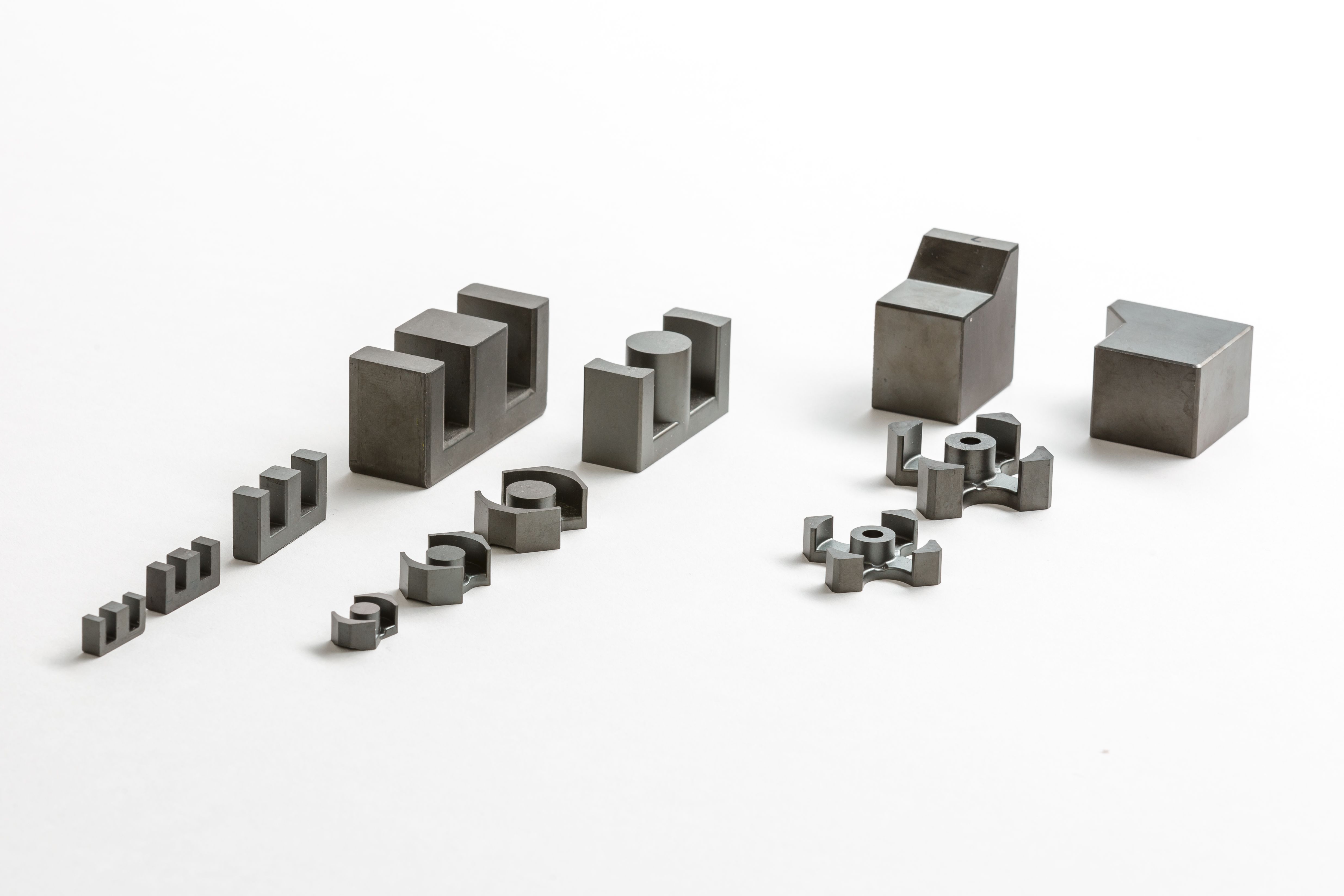
THE CORE SIZE—-E, EF, EFD, ETD, P, RM, U, TOROID
The following table shows which core types for your transformer could be considered suitable for the different converter topologies
Core type | Flyback | Forward | Push-pull |
|---|---|---|---|
E cores | + | + | 0 |
ETD cores | 0 | + | + |
EC cores | – | 0 | + |
U cores | + | 0 | 0 |
RM cores | 0 | + | 0 |
EP cores | – | + | 0 |
P cores | – | + | 0 |
Ring cores (toroid) | – | + | + |
+ Favorable, 0 Average, – Unfavorable.
Related Resources

Choosing Transformer Cores for different SMPS topologies
The selection of the magnetic components to be used in a Switch Mode Power Supply (SMPS) design is the most important element of that process. During this, understanding the topologies of SMPS’ is crucial as the designer must consider the trade-offs between them. This article will give you an overview of these tradeoffs.
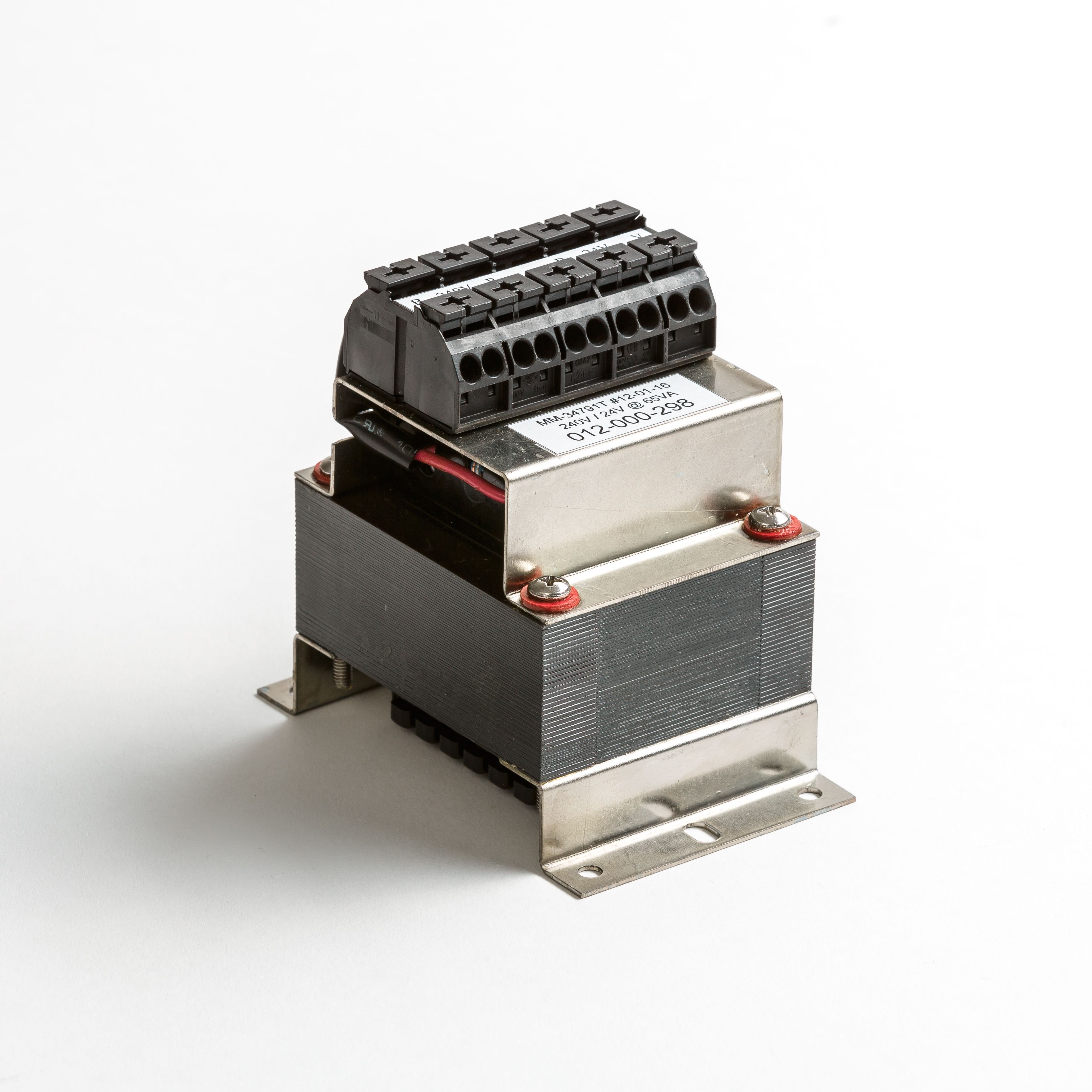
Using core VA ratings to determine transformer dimensions
I am writing this to share my views and experience in the design of magnetics (transformers and inductors), something in which I have been involved for most of my professional life. As in any design process, there are a number of critical parameters that must be met in order to achieve “success” and they are all intricately interrelated.