Common mode chokes (CM chokes, also known as line filters) are widely used in switch mode power supplies (SMPS) to suppress conducted and radiated interference as needed to meet the requirements of international electromagnetic compatibility (EMC) standards.
The finished product should not introduce serious electromagnetic pollution into the public electromagnetic network and at the same time be protected from electromagnetic disturbances emanating from the same environment. It is particularly worth mentioning that if the conducted interference (for the frequency range of 150kHz to 30MHz specified in EMC standards) can be effectively controlled, the radiated interference can also be dampened ( for noise frequencies > 30M MHz). Therefore, it is critical to design and select the appropriate common mode chokes, based on the strength and frequency of the electromagnetic interference, to get SMPS’s to successfully meet the appropriate standards. The more effectively and quickly this can be done, the less time and cost it will take to release a new product into the market.
It seems the most popular method for choosing a CM choke is to decide on an appropriate cut-off frequency from a L-Cy low pass filter. This is aimed at greatly reducing the conducted noise in a specific frequency range. But in order to restrict the leakage current of the product, it is obviously not desirable to make the value of the Y capacitor (Line to ground capacitor) too large because this leads to the CM choke inductance having to be as high as possible. The disadvantage with this is that the higher the choke’s inductance value, the larger its physical size and so engineers are forced into a costly trade off as CM Chokes are generally allocated a very limited space in the SMPS circuitry. Thus they end up having to find a CM choke that fits in the small allocated space and can only do so by using a higher permeability core which comes at an increased cost. There is a better way!
Cores commonly used in CM chokes are generally made with high permeability materials, starting at permeability of 5000 (5K) and going to 7000 (7K), 10,000 (10K), or even higher in MnZn ferrite materials. The important question is “Does the higher inductance of a CM choke give a better result in the suppression of/and immunity to EMI?”
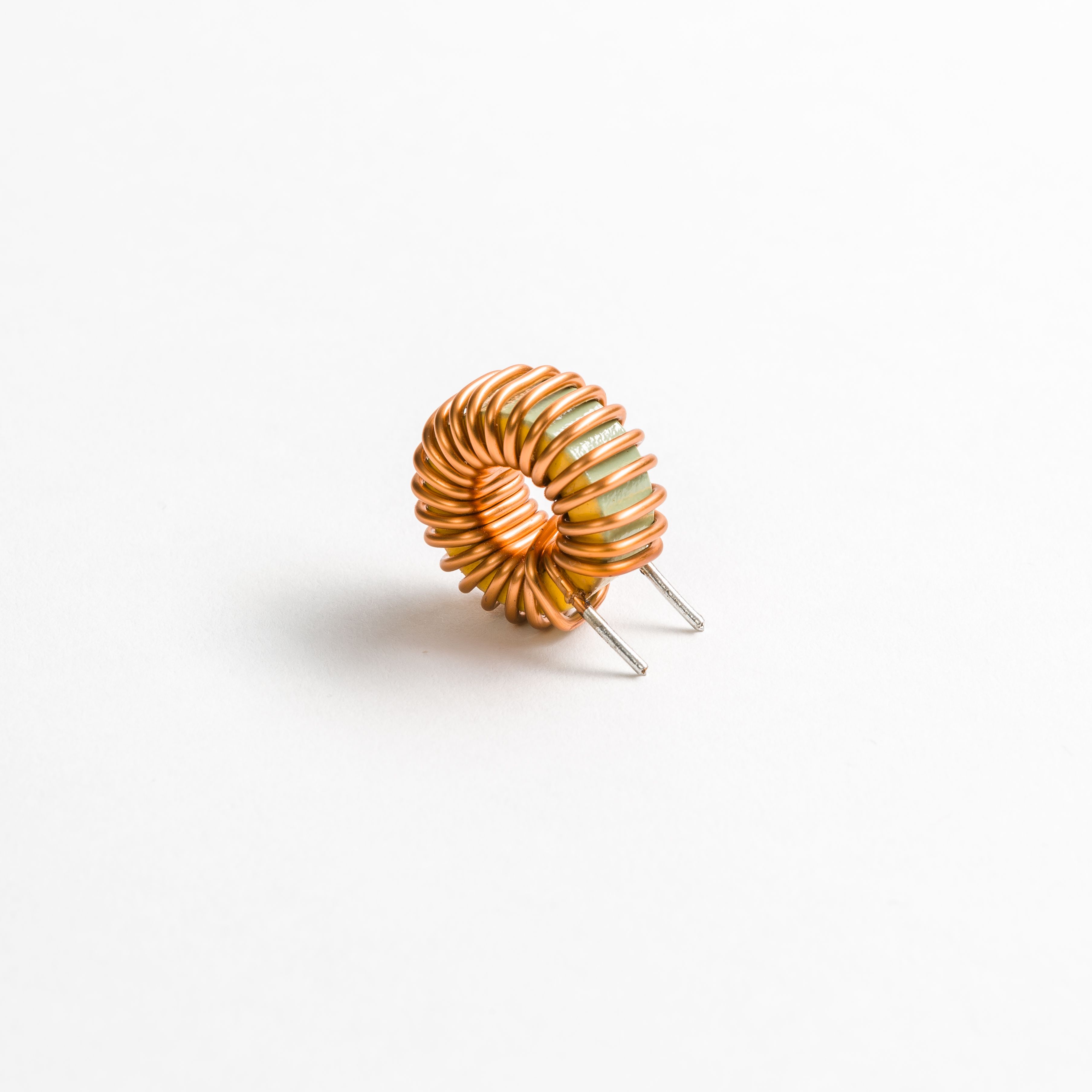
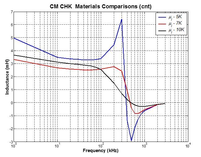
To gain insight into this issue, CM chokes with different core materials were first examined. Identically sized toroidal cores, wire gauge and number of turns were utilized in the test samples. Three sets of these samples were prepared, differentiated only by core material with initial permeability of 5K, 7K and 10K, respectively. An Impendence Analyzer was used to sweep frequencies from 10kHz to 120kHz on a single winding of these common mode chokes. The inductance and impendence frequency characteristics obtained are shown in Fig. 1 and Fig. 2 respectively.
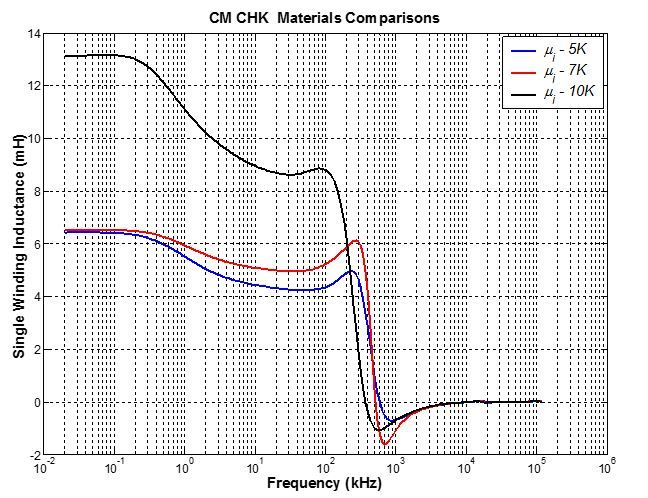
Fig. 1 results show that inductance is proportional to the core material’s initial permeability. The higher the core material initial permeability, the higher the inductance the CM Choke has with the same number of turns and same core size. The inductance of a 10K material choke has almost twice the inductance of a 5K material choke when the choke works under 100kHz, while the inductance of a 7K choke is only slight higher than that of the 5K material choke in the same frequency range.
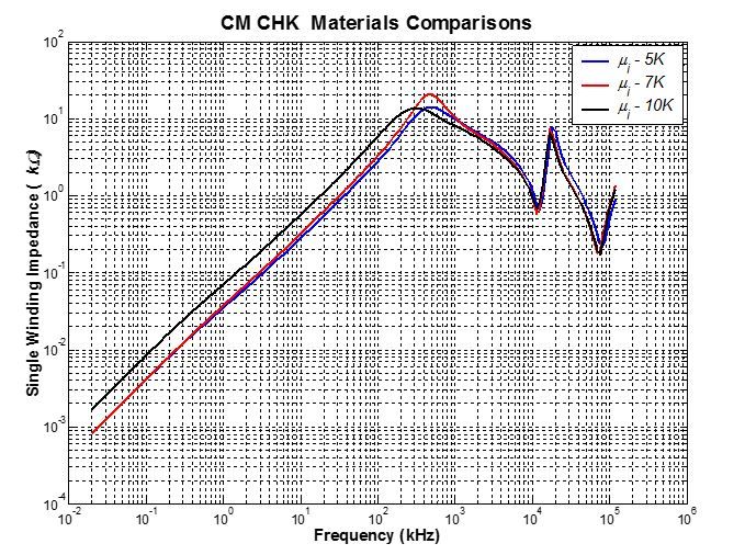
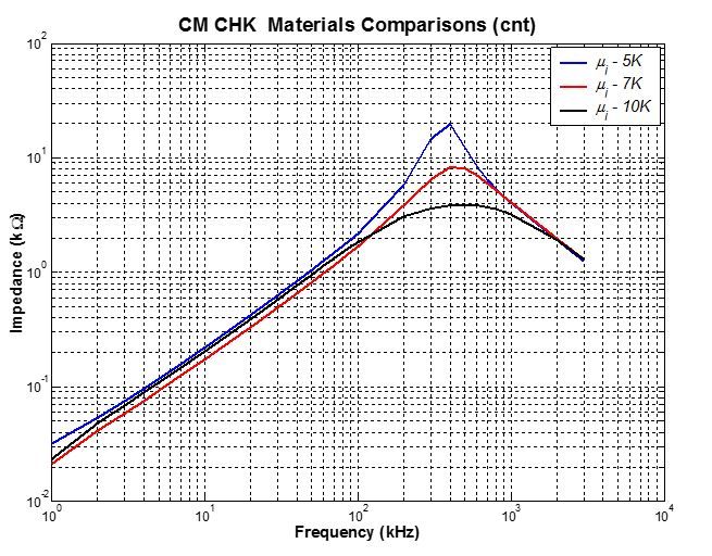
But the impedance measurements do not mirror the performance of the inductance results, as shown in Fig.2. The higher core material initial permeability does not always give higher impedance. The best noise attenuation falls to the 7K material which has the highest impedance value at the frequency between 300kHz to 400 kHz. This frequency range is the optimum working frequency of the 7K core material. The 5K and 10K material have very close peak impedance values, but occur in different optimum frequency ranges. The 5K material choke has its peak impedance at the frequency around 400kHz, but the 10K material choke is found to have the peak impedance at the range between 200kHz to 300kHz. When the core material has higher initial permeability, the choke has a stronger ability to suppress low-frequency common-mode interference. If the frequency is higher than 200kHz, the 7K choke gradually leads the impedance over the 5K and 10K materials. However, the 7K material choke has a sharp bell shape curve compared with the 5K and 10K material whose impedance curves are much smoother in the neighbourhood of the peak impedance values.
A strong indication is therefore revealed here that the proper way to design and choose a CM choke should not only take into account the inductance, but also the frequency range within which the interfering frequency occurs. Thus the appropriate core material should be chosen to get an optimum EMC suppression result without oversizing the component or going to costlier higher grade materials.
To obtain similar inductances on identical sized toroidal cores with different core materials, the CM chokes were then wound with different numbers of turns using the same wire gauge. Here we target chokes with inductance in the frequency range from 10kHz to 100kHz. The performance of these CM chokes is shown in Fig.3 and Fig.4, respectively.
The inductance curves shown in Fig.3 reflect the optimum operating frequency of the different materials. The frequency corresponding to the inductance at zero in Fig.3., coincides with the frequency where the maximum impedance occurs in Fig. 4. (Note: The frequency at that point is called a Zero Phase Angle (ZPA) frequency.)
It is well known that a higher number of turns are required for a lower permeability core to have the equivalent inductance of a higher permeability core. When increasing the number of turns, the result is increased inductance AND capacitance, the latter increasing at a slower rate, as can be appreciated in Fig.3.
The impedance curves in Fig.4 illustrate that the more the number of turns on a CM choke, the stronger the interference mitigating capability the choke has. The peak impedance value of the 5K material is nearly two times of that of the 10K material’s, even though their inductance is quite similar. The higher number of turns also means an increase in the copper loss in the choke, making it less attractive as overall product efficiency is always a key consideration.
On the other hand, the optimum frequency span is totally different for different core materials. Among the three types of CM chokes, the 5K core material choke has the sharpest shape. The optimum frequency span (band width) of the 10K core material choke is wider and we strongly recommend its use in those SMPS circuits which have conducted interference at a much lower frequency range.
So it is clear that the core material determines the interference mitigating frequency range, while the number of turns determines its interference mitigating capability.
Considering the overall performance of these CM chokes, the 7K material has displayed not only the better performance in the high frequency band than the 5K material, but also has shown a wider interference mitigating frequency band similar to the 10K material’s performance. Therefore, the 7K core material chokes should be the first to be considered by design engineers.
Should you have a CM choke requirement, please refer to above Fig. 5 curves, which correspond to our “off the shelf” CM choke products.
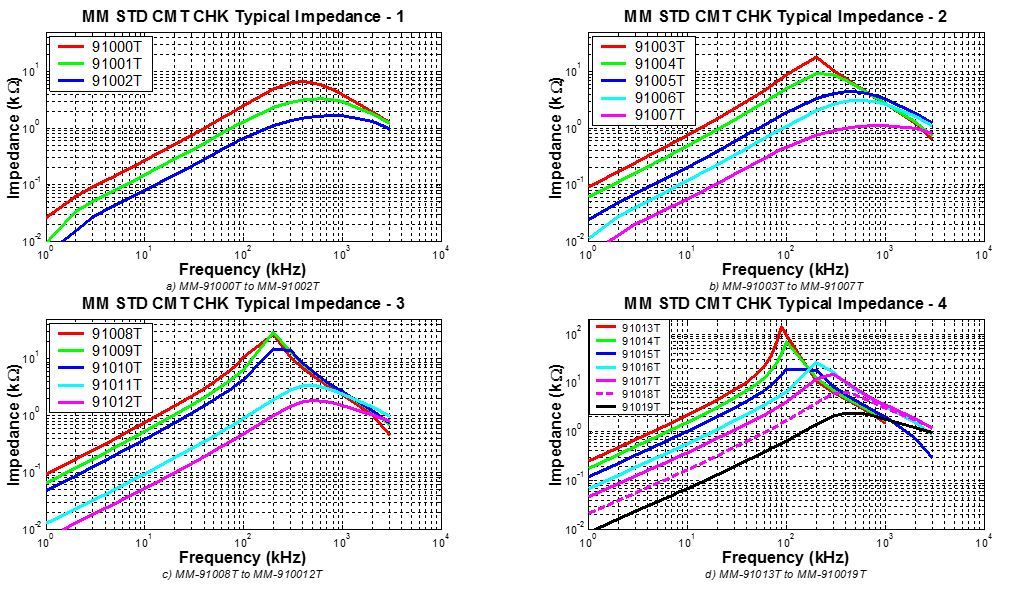
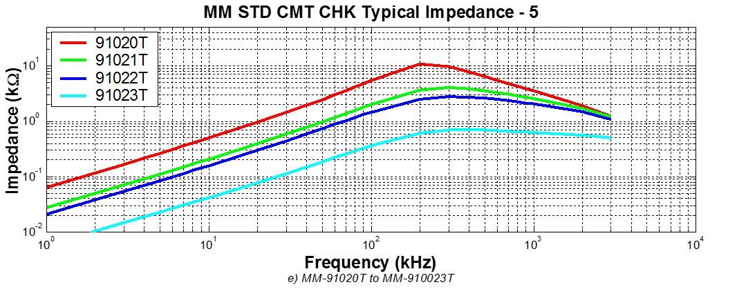
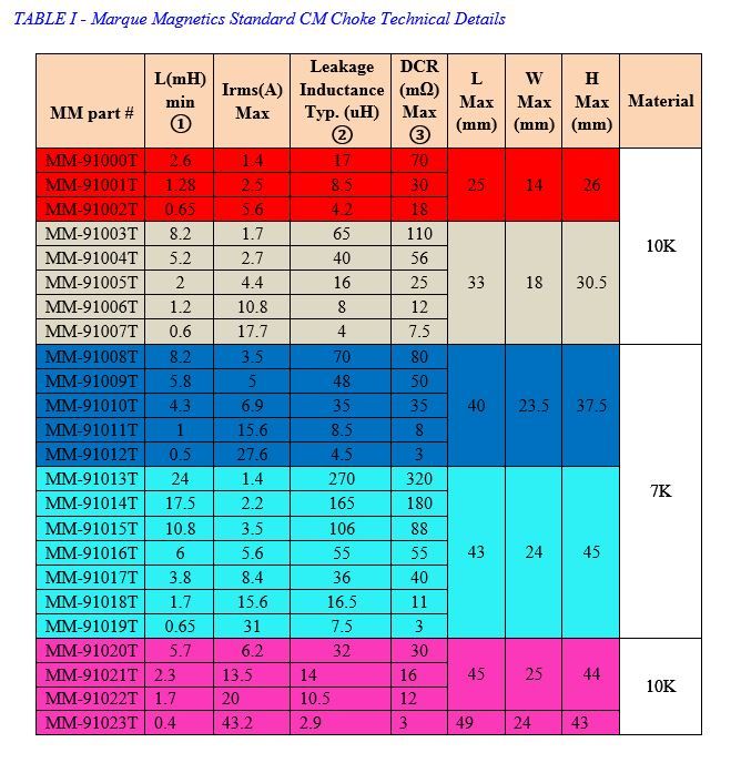
Table I presents more detail on our standard CM chokes. If you need one outside this table, we can provide you with a customized choke to for your application.
Marque Magnetics, your reliable choice for wound components!
Related Resources

Common Mode Chokes – Selecting the right one
Common mode chokes (CM chokes, also known as line filters) are widely used in switch mode power supplies (SMPS) to suppress conducted and radiated interference as needed to meet the requirements of international electromagnetic compatibility (EMC) standards.