Resources

The Power Transfer Capability of Transformers
This problem, in fact, is about the transformer’s power transfer capability. To address this question, a good start is from a transformer equivalent circuit. In theory, the ideal power transformer is a device that neither produces, stores, nor consumes any energy. It only transfers the power from the power network to the load by changing the primary and secondary voltage in accordance to the fixed turns ratio. However, in reality, due to the intrinsic losses of iron cores (core loss) and the presence of winding resistance (copper loss), the power of the transformer is not 100% transferred, so the input and output voltage of the transformer is not a simple relationship of turns ratio. This can be explained from the dual port equivalent circuit of the transformer in this article
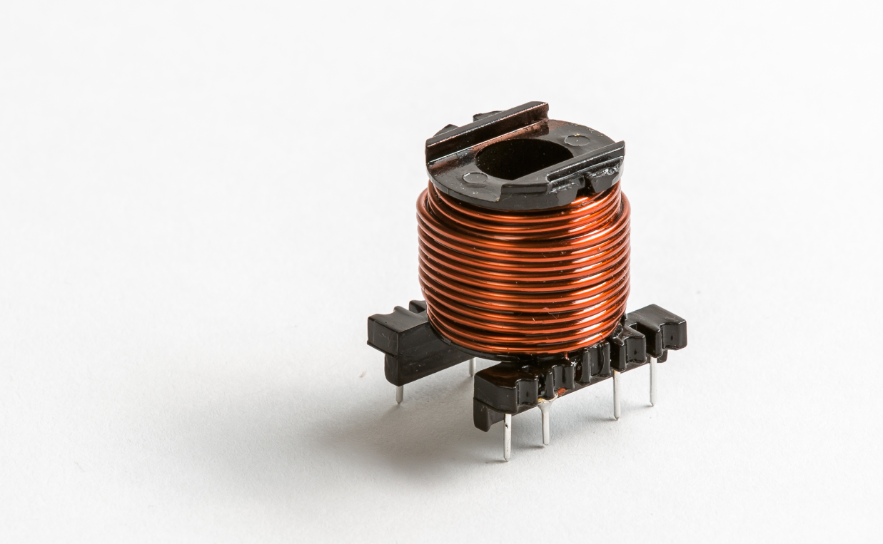
Choosing Transformer Cores for different SMPS topologies
The selection of the magnetic components to be used in a Switch Mode Power Supply (SMPS) design is the most important element of that process. During this, understanding the topologies of SMPS’ is crucial as the designer must consider the trade-offs between them. This article will give you an overview of these tradeoffs.
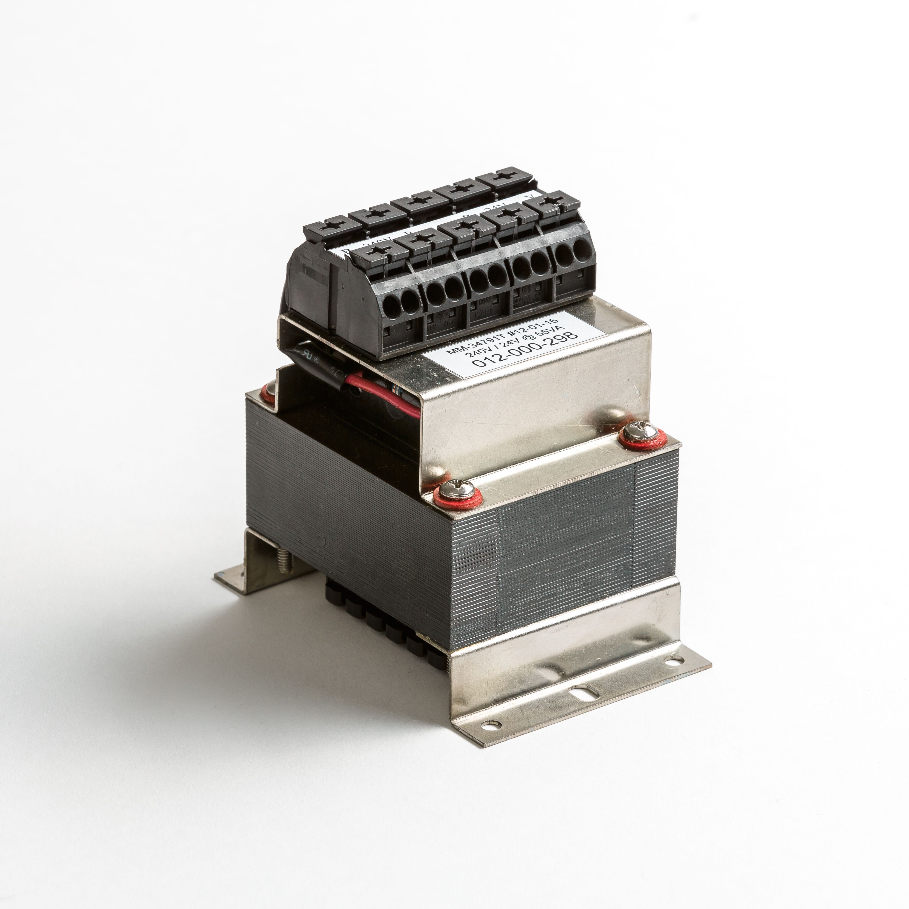
Using core VA ratings to determine transformer dimensions
I am writing this to share my views and experience in the design of magnetics (transformers and inductors), something in which I have been involved for most of my professional life. As in any design process, there are a number of critical parameters that must be met in order to achieve “success” and they are all intricately interrelated.